
CTX beta 2000
Universal turning center
Max. workpiece diameter
31 in.
800 mm
Max. workpiece length
79 in.
2,000 mm
Max. bar capacity diameter
4 in.
110 mm
Max. X-axis stroke
16 in.
415 mm
Max. Y-axis stroke
6 in.
150 mm
Max. Z-axis stroke
80 in.
2,025 mm
Control & software alternatives
SIEMENS
Highlights
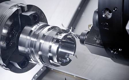
High Precision Turret for the highest accuracy with 4,000 rpm, 12,5 kW and 85 Nm
- <10 μm tolerance in diameter
- <10 μm thermal stability by active cooling
Machining of workpieces up to Ø 600 mm turning diameter and up to 2000 mm turning length
- Max. chuck diameter 500 mm
- VDI 50 turret with 12 driven tool positions + 6 Blocktool
- NC tailstock and steady rest (options)
Machining of workpieces up to Ø 600 mm turning diameter and 2.000 mm turning length
- Circular diameter up to 800 mm
- Bar machining of workpieces up to Ø 111 mm
- Mainspindle ISM 102 with 4.000 min-1, 45 kW and 770 Nm Standard, optional ISM 102 plus with 2.500 min-1, 52 kW and 2.200 Nm

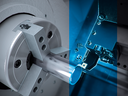
Accuracy
- Maximum stability and long-term accuracy
- Maximum thermal stability thanks to water-cooled, integrated spindle motors
- Unrivalled long-term precision with linear scales in the X-axis as standard
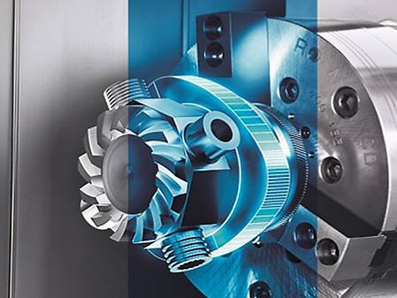
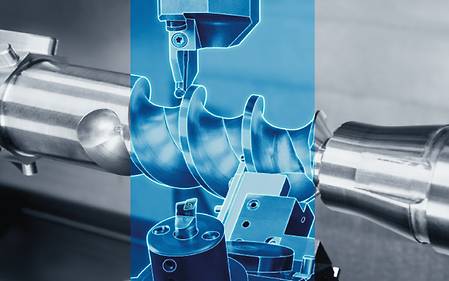
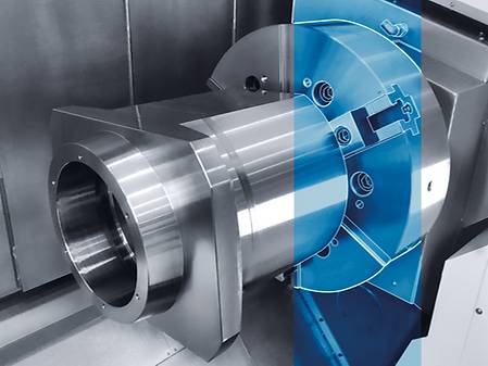
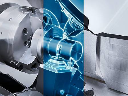
Application Examples
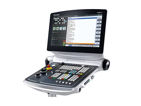
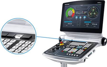
Control & Software
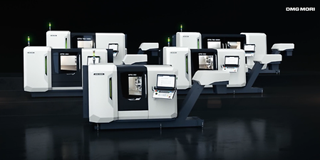
Experience the speed of digital transformation (DX)
Revolutionize your operations, unlock new opportunities, increase efficiency and promote sustainability by reducing power consumption – while gaining a strong competitive advantage.
SIEMENS SINUMERIK 840d solutionline Operate

- Shopturn Workshop-orientated programming
- Advanced Surface and Top Surface: best workpiece surfaces with minimum processing time
- Extensive machining cycles
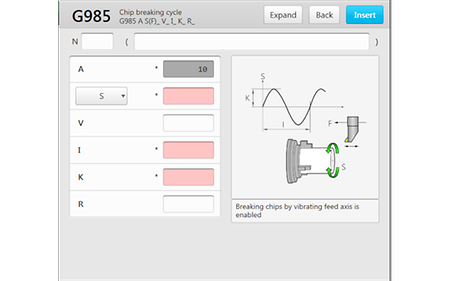
Chip Breaking
- Oscillating movement of the feed axis results in air cutting, which leads to effective chip size reduction
- For external longitudinal turning of internal and external diameters, facing, drilling and grooving*
- Integrated safety function checks plausibility of parameter entries
* For inclined surfaces, a step pattern results because the feed can only be oscillated in one axis at a time.
Highlights
Customer benefits
Before the actual machining, the machining status can be checked by using a graphic
- The chip length can be practically determined by the cycle and is independent of the material
- No more process interruptions, as chip balls are avoided
- Easy setting on the HMI with high operating safety
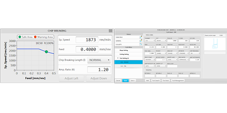
Left: The oscillation can be set with the simplest parameter inputs / Right: Simply activate it by ON / OFF in the HMI
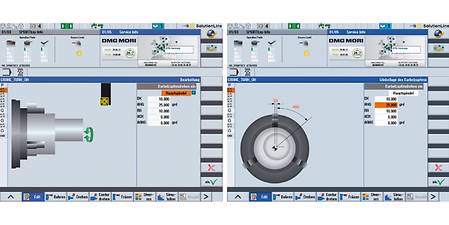
Polygon- / Oval-Turning
- Easy handling of non-circular parts
- Intuitive user interface for polygons / oval turning
Highlights
Customer Benefits
- Making the required geometries with possibilities of simple fine-tuning
- Possiblity of fine tuning of the geometric parameters (long / short Semi-axis and bearing angle)
- Machining can be combined with main spindle or counter spindle
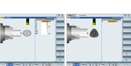
Left : Pre-position and support position in X and Z-axis can be directly entered over the surface. / Right : Monitoring of the support position via a defined Position window.
Control of program status
- In combination with the Gildemeister structure programming, A safe and fast reboot of the machining program after an interruption
- Easy program operation especially with multiple spindles or tool magazine
- Displays the process status of the workpiece
Highlights
Customer Benefits
- Display of the detailed status on the controller
- Enter remarks automatically by the GILDEMEISTER structure programming.
- Safe re-entry into the program by the press of a button instead of searching for a specific block.
GILDEMEISTER Structural Program
- Structured approach with more than 20 standard programs and more than 200 processing variants incl. automation (bar processing, robot / portal loading, ...)
- Display of the program status with additional markers (EPS) for the sub-programs.
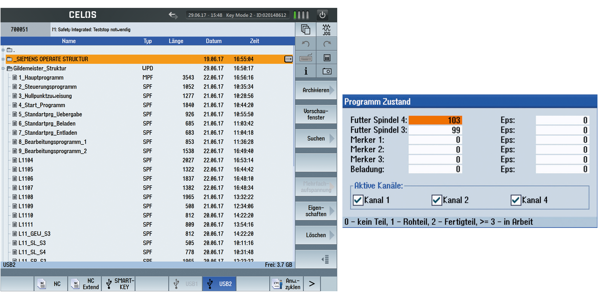
Left : HMI with markers status. / Right : Clear program structure.
Y-Axis Parting
- Higher stability due to optimal force transmission in thelongitudinal direction of the tool holder
- Generation of tool feed in the Y-direction for parting off components at a push of a button
- Compatible with the standard cycle CYCLE92 (Part off cycle), so that the operator can program as usual (ShopTurn and DIN / ISO)
Highlights
Customer Benefits
- Up to three times higher productivity possible (3x feed) with simultaneously improved chip control
- Reduced noise level and higher surface quality through more tool stability
- Less material loss due to reduction of the parting width
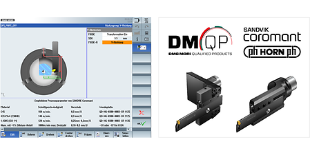
Left : Operator mask for switching on the Y-axis parting cycle on turret and turn-mill machines. / Right : CoroCut® QD for Y-axis parting cutting tool technology developed by Sandvik Coromant.
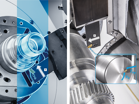
Counter spindle tip
- Perfect combination of 6-sided complete machining and tailstock function
- Automatically load and unload a tailstock centre into the chuck of the main spindle or counter spindle via the milling spindle and into the mgazine
- Support of long and slender workpieces on the main spindle thanks to the synchronous counter spindle tip
Highlights
Customer Benefits
- Higher component accuracy due to automatic change without opening the door (heat flow constant)
- Position-locking the spindle with the tip leads to increased process safety
Left : Automatic changed centering tip. / Right : Parameter Input Mask: Control Cleaning, changing tip and control coolant
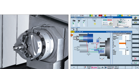
Keyway Broaching
- Structured input parameters for the groove geometry, the tool and the machining strategy
- Inner and outer grooves in any position and number freely adjustable
- Easy compensation of tool displacement + Calculation of residual strokes based on selected machining strategy
Highlights
Customer Benefits
- High flexibility in the production of any groove geometries with standard tools on standard machines
- Reliable alternative when pushing with driven tools is no longer an economical or technological solution
- Advantages of rigid machine guidance for better groove quality
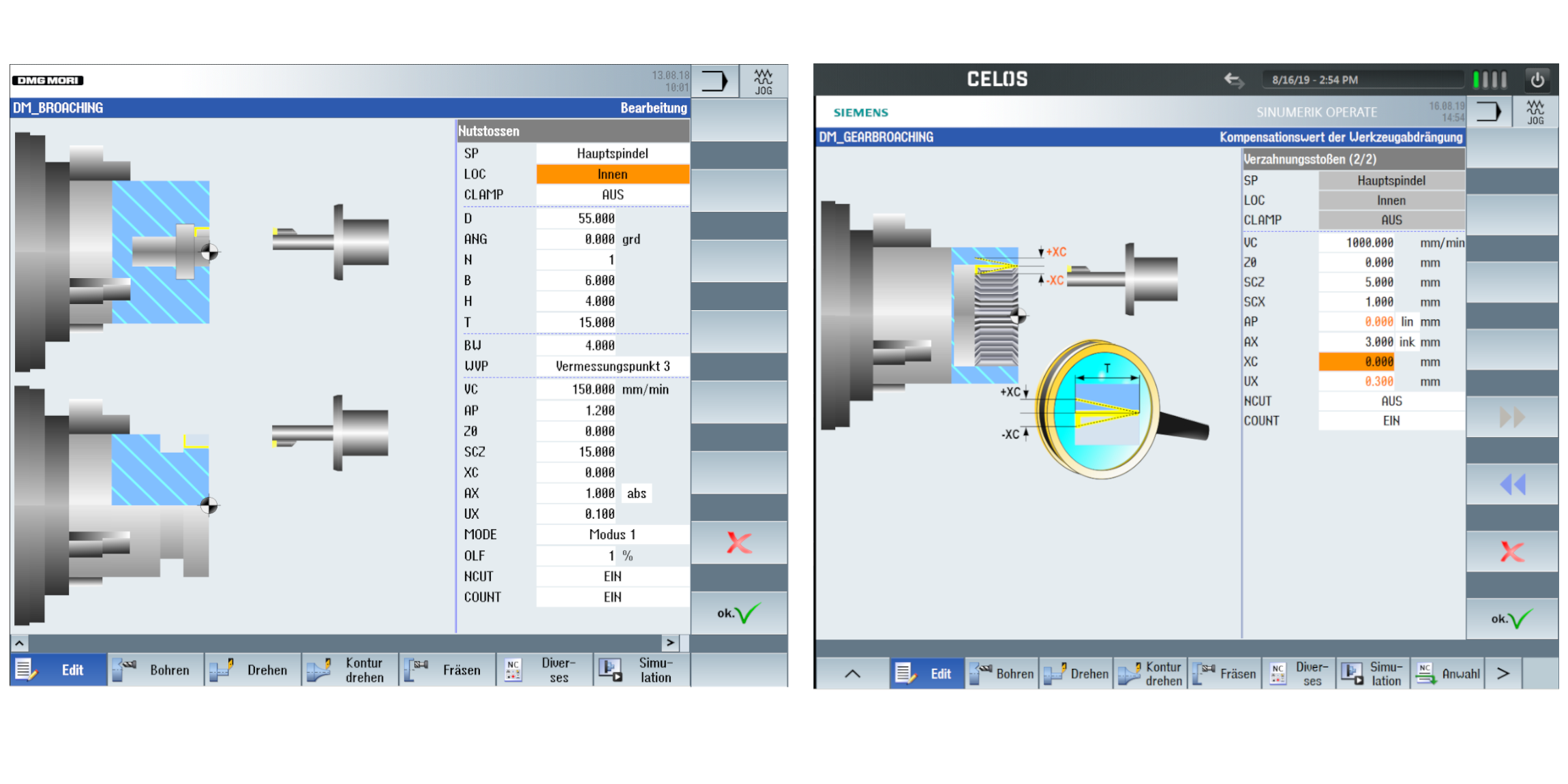
Left: Input mask for inside and outside grooves according to DIN with standard tools. / Right: Input parameters of the process strategy: Compensation of tool displacement
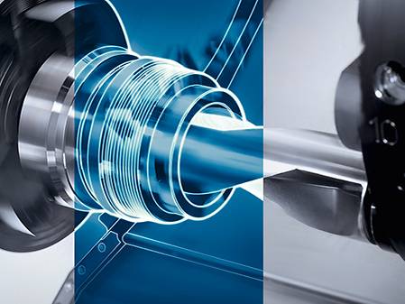
Multi Threading 2.0
- NEW: On-Point Threading - Position oriented thread production
- Free definition of contours, pitches and gears possible
- Creation of large transmission threads, which can not be manufactured by simple thread chasing
Highlights
Customer Benefits
- Trapezoidal, buttress and knuckle thread easily programmable at the machine
- Screw conveyor with any profile geometry
- Ball screw nut with cross holes simple to realize
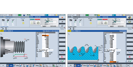
Left : Input of the parameter for thread length, position pf the thread and the distance of the retract movement. / Right : Parameters for thread shaping, e.g. profie height, pitch diameter, etc.
Multi threading 2.0 Pro
Highlights
- Producing profiles with undercut due to the profile splitting option.
- Applying standard tools and tool holder for left and right sided machining of the flanks
- Surface quality of Ra 0,3 an CrNi-Alloys possible
autoCHUCK 2.0
- Automatic optimization of servo drives parameters for Main- and Sub-Spindle
- Reduction of Setup time
- Optimization of machining result
Highlights
Customer Benefits
- Setup Time reduction
- Automatic determination of parameters independent from machine operator experience
- saving the setting in NC-program for more quality assurancet
Left: Simplified usability of measuring and parameter setting procedure / Right: Local saving of parameter in NC-program
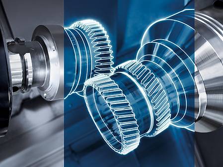
gearHOBBING
- Programming of the gearing parameters via dialog input
- For spur gear, helical gear and worm gear
- Gear cutters and disk cutters can be used
- Maximized tool life by shifting of the cutter
- Achievable quality ≤ DIN 7
Highlights
Customer benefits
- Gear profile modifications easy to handle
- Use of regrinded tools
- Error prevention by monitoring (e. g. wrong axis cross angle, or wrong turning speed, or turning direction)
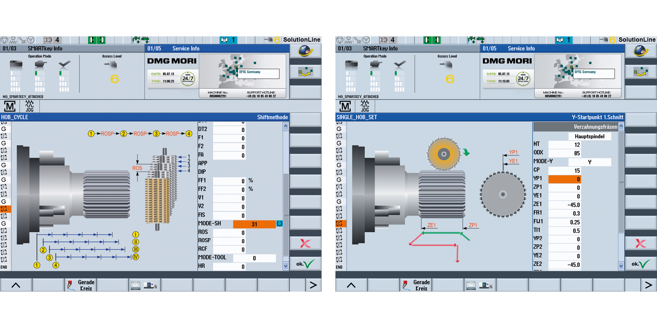
Left : Dialogue-supported input of all necesary gearing data. / Right : Input of the gearing paramters by single tooth or single groove milling.
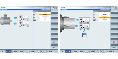
Alternating speed
- Easy to operate through three parameters and without additional sensors
- Avoiding vibrations by means adaptation of the speed
- Application for the main spindle and counter spindle, or for milling machines with FD tables with Direct Drive
Highlights
Customer Benefits
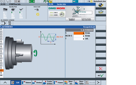
Input of parameters for speed set-point, differential speed and revolution frequency
- No manual intervention by the operator
- Identical repeatability for all components
- Increased process safety for special applications by avoiding vibrations. example, When using long thin drills or for milling parts with critical clamping
gearSKIVING 2.0
- Straight and helical external or internal spur gears and splines
- Arrow teeth with tooth offset Turn-mill machines
- Ball-shaped toothing by mathematical transformation of the 6th virtual axis
Highlights
Customer Benefits
- Internal toothing without angular head possible
- Short processing times, 10 x faster than shaping
- Synchronization and tool path controlled by the Cycle

Left : Inside gear profile machining. / Right : Outside gear profile machining.
Easy Tool Monitor 2.0
- Prevention of damage due to tool breakage or tool overload
- Sensorless with automated learning of load limits
- For turning, milling and drilling (up to 3 mm diameter)
- NEW: User interface on CELOS SideScreen
- NEW: Powerful algorithm for efficient monitoring after the first workpiece
Highlights
Customer Benefits
- Protection Package: Perfect supplement to MPC Lathes. Price advantage (approx. 40%)
- Save the monitoring limits for each tool and every cutting edge in the program
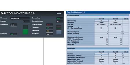
Left : LIVE status display in CELOS Sidescreen; current, set process values. / Right : Easy operation of the monitoring parameters in the tool table.
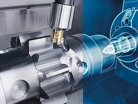
Excentric turning and milling
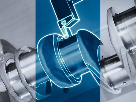
- Superposition of the turning movement by additional X- and Y-traverses
- Applicable for turning and milling
Highlights
Customer Benefits
- Eccentric geometries easy to manufacture
- Exact axis coupling and synchronization in the background
Left : Enter the parameters for the position of the external workpiece area. / Right : Graphical representation of the position within the workpiece.
Retraction Cycle
- By pushing the associated key the X- axis and the Y-axis travel to the positive end-positions for external machining
- Ideally suited to prepare the work space for set-up and alternatively also as an emergency rescue function.
Highlights
Customer Benefits
Functionality - Selection of the cycle by pressing the associated key on the operating panel
- Easy operation when setting up multi - channel machinery
- Possibilty of a fast response during external machining as a rescue function
Service & Training
Comprehensive carefree service and training for your production
Take advantage of our full-service offering and hands-on training to maximize machine performance and minimize downtime. With comprehensive maintenance packages, original spare parts and tailored training programs, we can take your production and your team to the next level.
Downloads & Technical Data
Work Area
Max. X-axis stroke
16 in.
415 mm
Max. Y-axis stroke
6 in.
150 mm
Max. Z-axis stroke
80 in.
2,025 mm
Workpiece
Max. workpiece diameter
31 in.
800 mm
Max. workpiece length
79 in.
2,000 mm
Max. bar capacity diameter
4 in.
110 mm